Architecture (4.x version)
Introduction
This part deals with the description of the Code_TYMPAN architecture. Each section represents a part of the code and describes how it is organized:
main organization of the code and the different parts
some dependencies between these different parts
what kind of objects you will find in the different part
Description
Code_TYMPAN is made of different parts:
core&tools
graphical user interface
business logic
geometric libraries
solvers
An API in Python is used to communicate between the Graphical User Interface (GUI) and the solvers.
Three classes of users may interact differently with Code_TYMPAN:
The basic user will use the GUI which builds the data models and run a calculation through the API
The advanced user may drop the GUI and runs a build the model/run the calculation with the API
At least, the programer will add new solvers/features on the C++ solver part and the API part
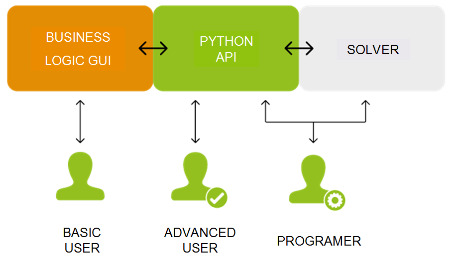
Parts separation in the 4.x architecture and how different users interact with Code_TYMPAN
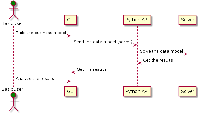
Sequence example for a basic user
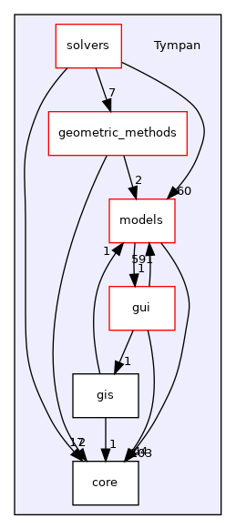
If we have a look on the source directories (folders) of the differents parts, the main relations in the current architecture are:
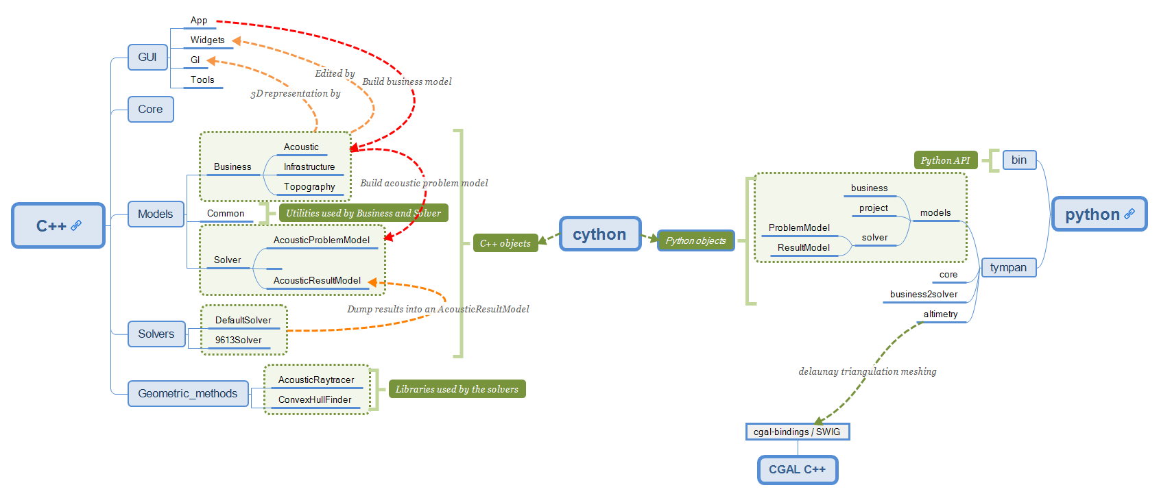
Current architecture schema
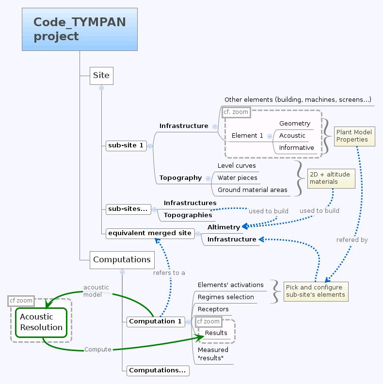
Here a second graph about the splitting between site elements (business logic) and the computation (solvers). It separates the business logic related to a site with the way to solve the acoustic problem (tympan::AcousticProblemModel). This solver data model, which can be used by any solver, is built from the Python subprocess by going through the current site and extracting relevant data: a computation needs triangles with materials from a site triangulation, acoustic sources/receptors and an altimetry.
Target architecture schema
- At the Tympan sources root, we find five directories:
core: Several tools classesmodels: Data model for solvers and business logicgui: Graphical User Interfacegeometric_methods: Geometric methodssolvers: Solvers
Main directories and dependencies
As several dependency graphs will be used below, we explain how it should be read:
Doxygen rules for dependency graph
Core and Tools
See the core and gui/tools directories and some sub-directories in models directories:
models/business: the main base class TYElement used for every business logic objects. Also implements an interface for the solvers and some XML tools in order to export/import a Code_TYMPAN study ;
models/common: common objects used by the Business Logic objects: point, vector, matrix, etc.
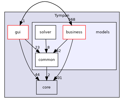
models directories and dependencies
The rationale behind the creation of models/common is to provide
basic representations and utilities which do not depend upon
TYElement nor OPrototype. Typically such representations and
utilities are likely to be shared between the main application and the
solvers.
The way the CGAL library is used deserves a special explanation. CGAL is a very powerful but quite complex templates-based library. As such dependency to CGAL appears in the headers of the client code and this has a heavy impact on compilation time and apparent code complexity.
In order to mitigate those drawbacks while benefiting from the CGAL features a variant of the classical Bridge* design pattern is used (For design pattern the key reference is [DPGoF] ).
Namely the cgal_tools module in models/common builds some
high-level functionality (constrained triangulations and domain
meshing) upon CGAL features ; its API relies on CGAL types and does
not depend on other Tympan types.
The cgal_bridge module in models/business exposes interfaces
to those features expressed with the main Tympan datatypes and ensures
the conversions.
This allows independent development and testing and reduces compilation times by breaking header dependencies propagation thanks to the bridge between the interfaces seen by the client code and the implementation.
Design Patterns E. Gamma, R. Helm, R. Johnson, J. Vlissides - Adisson-Wesley
Models data
See the different sub-directories in models:
business: objects which describe a site, acoustic objects (sources, receptor, paths), materials, machines, etc.
solver: the current work which describes a data model for the solvers.
Business Logic
Note
Business Logic is the part of the code which is not technical. Deal with “real life” models: buildings, machine, fields, etc.
Code_TYMPAN offers a way to build the business objects from
a string representing their class name. This feature (mostly used during XML
deserialization) is implemented in the OPrototype class through a factory
pattern. To use this facility, it is first necessary to register all the objects
that will need it. This is handled by the init_registry() method
(from models/business/init_registry.h), that must be
ran before any call to the methods specified by OPrototype interface.
For now, the splitting between the business logic objects and the Graphical User
Interface is not clear. In other words, you can have a strong dependency
between models/business and graphical widgets described in
gui/widgets. One of the objectives described in the section is to split these parts.
Solvers
It makes a dedicated data model for the solver part (see class tympan::AcousticProblemModel), i.e. create elementary objects (as opposed to business objects) such as acoustic sources and receptors, triangles related to a material, spectrums, etc. in order to define a model that can be used by any solver.
Graphical User Interface
See in Tympan/gui and its four sub-directories:
tools: common tools and objects used for the GUI ;
widgets: widgets such as buttons, boxes and some widgets dedicated to a specific business logic objets such as a building, a field, a spectrum, etc. ;
gl: 3D representation of business logic objects such as a building, a machine, etc ;
app: GUI main classes.
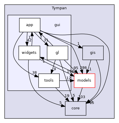
GUI directories and dependencies
App
The app package is the place where the simulation workflow is split in
order to delegate some of the processing to a Python subprocess (see launch() method
from TYCalculManager class).
When asked to perform a simulation, the computation manager:
Serializes the current project to a XML file
Calls a subprocess running
solve_project.pypython script that uses Tympan libraries to:Read the serialized file
Build a data model representing the acoustic problem
Run the simulation
Serialize the computed project (with the results)
Reads the simulation results from the file serialized by the Python subprocess
Updates the current project with these results
Rendering
OpenGL is used to render the 3D viewport of the application.
Warning
We are in the process of migrating from a deprecated feature set of OpenGL (available through a compatibility profile) to a newer one named the Core profile.
Legacy OpenGL API
The legacy API is based on a Fixed Function Pipeline (implemented by drivers), which provide a basic configurable shader which allows lighting and texturing. This legacy API allow to draw 3D primitives using an immediate mode approach:
the 3D canvas can be rotated/translated/skewed (and theses transformations can be stacked) by calling some matrix manipulation functions:
glPushMatrix(), glPopMatrix()
glLoadIdentity()
glMatrixMode(GL_PROJECTION /* GL_MODELVIEW */)
glRotatef(), glTranslate(), glScale()
glOrtho(), glPerspective
and so on…
the pipeline can be configured to choose how primitives are rendered
and finally, calls to glBegin()/glEnd() declare a draw operation. Between these two calls, vertices can be added and parameters can be added to them by using functions such as:
glVertexf() to add a vertex
glColor to set its color
glTexCoord* to associate it to a coordinate on a texture
etc.
Without more configuration the elements are (in theory) drawn to the framebuffer as soon as glEnd() is called. To avoid re-sending the same primitives data (and the same rendering commands) to the graphic card on each render, most of OpenGL commands can be cached in display lists. Any rendering operation executed between glNewList(myListId, GL_COMPILE) and glEndList(myListId) will be replayable by using glCallList(myListId). With display lists, the graphic driver is able to cache already done computation and reduce communication between the CPU and the GPU by storing primitives once in GPU memory.
Note
You can find the list of all functions and values from compatibility profile
that are not present in latest core profile
here. You can provide this file to grep to find all references
to them in Tympan code base grep -rf ./doc/deprecated-gl.txt ./Tympan/gui.
OpenGL Core profile
OpenGL 2.0 dramatically changed the way developpers interact with the graphic card, by moving from the Fixed Function Pipeline to a programmable pipeline, based on compiled shaders and new way to declare geometries.
Shaders are responsible for converting geometry into colored pixels. Shaders are programs written in GLSL which is a language whose syntax is similar to C. There are several kinds of shader, each executed at a different time in the pipeline. You can find an overall description of the OpenGL rendering pipeline on the OpenGL wiki.
For us, the most important shaders are the following two:
vertex shaders take a stream of vertex data as input and emit vertices and their attributes.
fragment shaders compute the color of a fragment (sub-pixel) from its coordinates and from interpolated vertex data.
Other shaders (compute, tesselation control/evalutation and geometry shaders) are less common, but might be useful for complex scenari.
The vertices sent to the vertex shader are stored on the GPU through the use of VBOs (Vertex Buffer Object). VBOs generally contain vertices coordinates, normals, color, texture coordinates, etc.
One advantage over the display list is that you can access these buffers and edit the data in a dynamic way, whereas display lists are static, in a sense that when the geometry changes you have to recompile/send the whole display list again.
Usage of OpenGL in Code_TYMPAN
Each project element has its equivalent graphical object, inheriting from TYElementGraphic, for example TYSiteNodeGraphic correspond to TYSiteNode. These TYElementGraphic objects have a display method which is responsible for calling the OpenGL drawing functions necessary to show their corresponding business element. Currently, Code_TYMPAN mainly relies on the fixed function pipeline, which means that a lot of functions removed from the core profile can be found in these display method.
The TYRenderWindow holds an OpenGL context and the framebuffers used to render pixels on screen. When a redraw is requested (because the project has been edited, because the window has been focused, etc.), its paintGL method delegates rendering to the TYOpenGLRenderer’s OpenGLRender method. This method setups the OpenGL context’s state and either execute some display lists or compile-and-execute them when they are considered as dirty.
Migration to newer rendering pipeline
Our goal is to be able to only rely on the OpenGL core profile. A big amount of code is doing direct calls to OpenGL legacy API, making the migration to a newer API tedious.
Our plan for this migration is to abstract these calls behind a render model usable by the renderer. Instead of calling OpenGL functions TYElementGraphic instances will provide OGLMeshInstance`s that bind a geometry with its material (`OGLMesh and OGLMaterial) to a transform (QMatrix4x4). All OpenGL calls will be colocated into the TYOpenGLRenderer class.
This modelisation is pretty common among industry softwares. It has several benefits :
these classes are a simple and understandable abstractions.
procedural meshes can be created by sub-classing OGLMesh, e.g. OGLCylinderMesh, OGLDiskMesh, OGLPlaneMesh, OGLPolylineMesh …
render model is independent from render API (OpenGL, D3D, Vulkan…) allowing to introduce another render API easily.
move all OpenGL calls into TYOpenGLRenderer;
def collect_instances(element):
   for child in element.children():
      if isinstance(child, TYMeshInstance):
         yield child
      else:
         yield from collect_instances(child)

def render_mesh(render_context, mesh, model_matrix):
   program = findOrCreateProgram(mesh.material)
   useProgram(program)
   setUniform("model_matrix", model_matrix)
   setUniform("view_matrix", render_context.view_matrix)
   setUniform("projection_matrix", render_context.projection_matrix)
   vbo = findOrCreateVBO(mesh)
   drawElement()

def render(render_context):
   for mesh_instance in collect_instances(render_context.modeler_element):
      model_matrix = mesh_instance.global_matrix
      if render_context.modeler_element in mesh_instance.parents():
         # Handle the case where the edited element is not the root element
         matrix = modeler_element.inverse_global_matrix * matrix
      render_mesh(render_context, mesh_instance.mesh, model_matrix)
The overlay elements and the grid/axes could also use OGLMeshInstance`s. To make creation of common shapes easier we could create pre-built meshes like `OGLCylinderMesh, OGLBoxMesh, etc.
Current status of the migration
At the time of writing, the following classes have been (partially) implemented:
OGLMesh and OGLBoxMesh
OGLSimpleMaterial
Currently TYOpenGLRenderer.cpp’s drawBoundingBox` function renders bounding boxes using the new render model.
It creates a GPU buffer to hold the vertex data (currently only position), and a Vertex Array Object (VAO) to manage the vertex attributes. The shader program is configured with the model, view, and projection matrices, and other shader uniforms are computed from the material. Another GPU buffer is created and filled with the indices used to draw the mesh. The bounding box is then rendered using glDrawElements for lines and glDrawArrays` for points, then all OpenGL resources are released and destroyed.
Remaining work
Currently, only bounding boxes are supported, we will have to handle meshes coming from TYElementGraphic objects.
The OGLMesh class still lacks some information:
which kind of primitives should be created when reading its indices array (lines, triangles, polygon, …);
the normal at each vertex;
the texture coordinates at each vertex.
The OGLSimpleMaterial class currently only allows specifying the mesh color. We will have to add more properties to handle all the currently rendered objects:
lighting mode (flat vs shaded)
texture
We will probably have to create a shader for the altimetry mesh. Its corresponding material (OGLAltimetryMaterial) will have to provide the heights of the lowest and highest points of the mesh.
The drawBoundingBox function could be made more generic to make it able to render any OGLMeshInstance. We could rename it drawMeshInstance or renderMeshInstance.
Currently, the OpenGL resources are destroyed at the end of each call. If we don’t want a drop of performance we should keep the buffer around between renders and only delete them when necessary.
Discover new possiblities
Picking
The picking is entirely done on the GPU by using a name stack and a selection buffer. This method relies on OpenGL deprecated functions and the steps are as follows:
We define a small “picking window”(5 pixel width) and we enter selection mode (a mode where the resulting rendering won’t be displayed).
We give a “name” (an integer) to each object we are willing to pick/draw.
The objects are then rendered. If a primitive falls inside the “picking window”, a “hit” occurs.
For each “hit”, the primitive with the smallest z-value (the closest one) is chosen.
The algorithm is located in the gui/app/TYElementPicker.cpp file.
Note
Actually, numerous names can be given to a primitive, that’s the reason why a stack is used. It enables the programmer to pick objects as a hierarchical structure.
There are two principal different ways of doing picking :
color picking ;
ray intersection.
The color picking uses entirely the GPU once again. We render every object with a unique color, then we read the color of the pixel under the mouse. This technique is straightforward and should be simple to implement, however we can’t get the coordinate of the intersection point.
The other method consists of a ray that we cast on the scene, and then perform ray-intersection test against the object of our scene. Usually, the ray go through an acceleration structure (e.g. grid, octree, k-d tree, etc), before being tested with the bounding box of the object. This method usually run on the CPU and is independant of the rendering API. It is easy to know the exact intersection point between our ray and the picked object.
Note
It might be possible to re-use the acceleration structures from models/geometric_methods/AcousticRaytracer/Accelerator for the ray-intersection method.
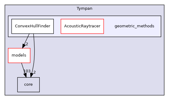
Geometric libraries
Three librairies are located inside the directory geometric_methods :
ConvexHullFinderLibrary used by the default solver only
AcousticRaytracerOnly few methods used by the default solver for altimetry computation
The last library is now completely independant from Code Tympan.
Geometric methods directories and dependencies
ConvexHullFinder

Dependencies
AcousticRaytracer
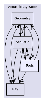
Dependencies
As AcousticRaytracer is now an independant geometric library for ray tracing, it is interesting to detail some of its classes. Here is the hierarchy of some of the mains classes of the library [legend]:
First, the Base classes which gather a lot of objects which constitutes the scene:
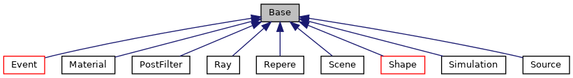
Base classes
The Sampler classes deal with the ray generators:
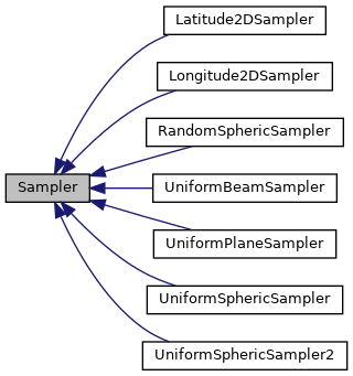
Samplers
The Engine classes is for the different ways to run the ray tracing method (sequential, parallel, …):
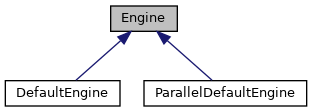
Engines
The Accelerator classes are used to select an efficient method for primitives classification:
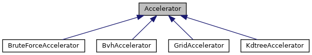
Accelerators
The Selector classes offers different criterias to keep or disable rays during tracing:
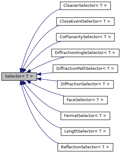
Selectors
Solvers
All directories in solvers :
Solvers directories and dependencies
DefaultSolver
DefaultSolverHistorical solver from EDF R&D, mainly inspired from 9613-2 norma and NMPB, being more physical and more accurate than 9613-2 norma.
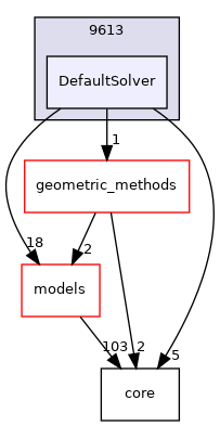
Dependencies
The collaboration graph [legend] of the DefaultSolver classes are:
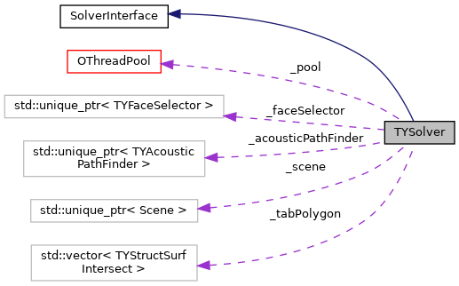
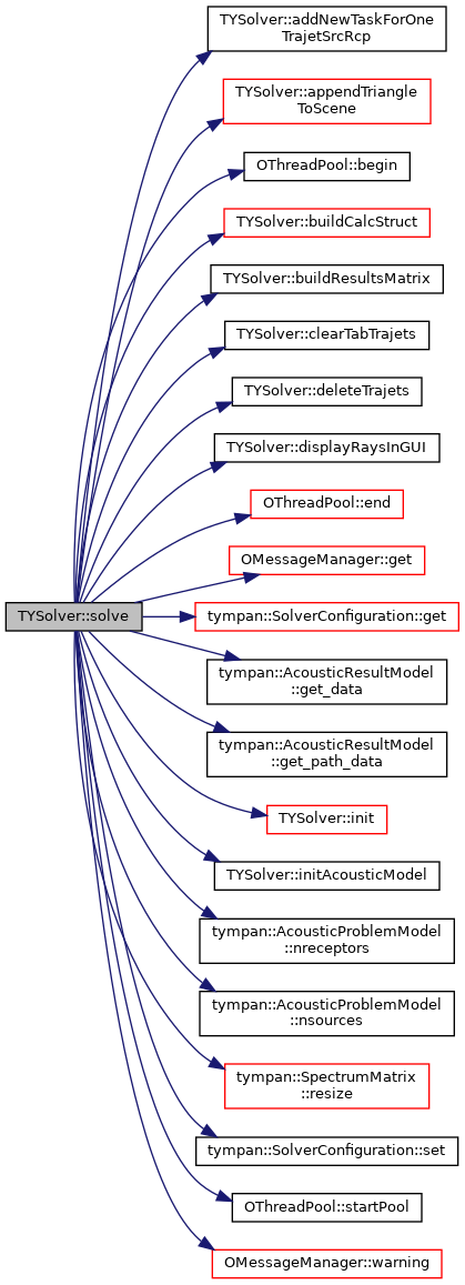
TYSolver class
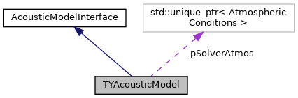
TYAcousticModel class
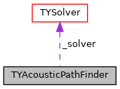
TYAcousticPathFinder class
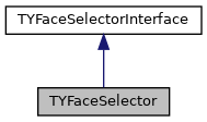
TYFaceSelector class
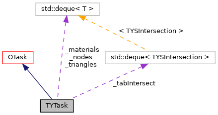
TYTask class
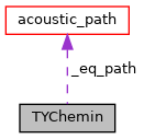
TYChemin class
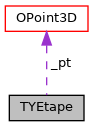
TYEtape class
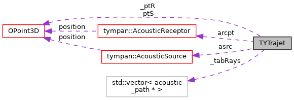
TYTrajet class
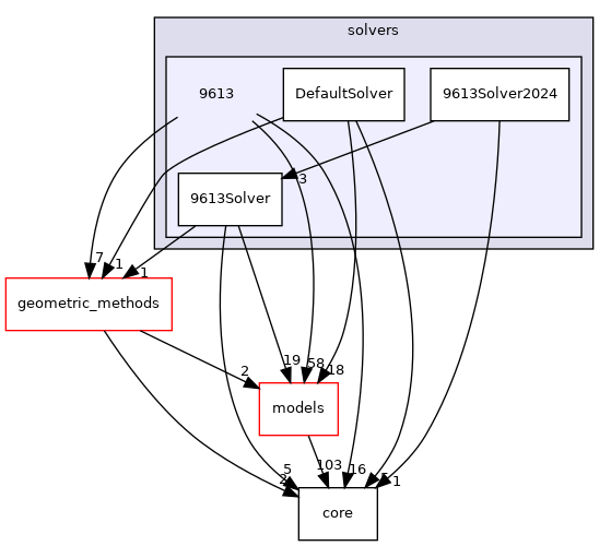
9613Solver
9613SolverSolver conforming strictly to 9613-2 norma
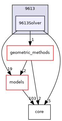
Dependencies
The collaboration graph [legend] of the DefaultSolver classes are:
TYSolver class
TYAcousticModel class
TYAcousticPathFinder class
TYFaceSelector class
TYTask class
TYChemin class
TYEtape class
TYTrajet class
Call graphs for Tympan solvers
First, it should be noticed than in the following Doxygen the order of calls graphs is NOT always from the top to the bottom.
The complete call graph for the default solver can be find here .
A simplified call graph is (click to enlarge):
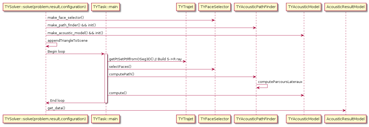
Default solver call graph
Python call graph to C++ solver (click to enlarge):
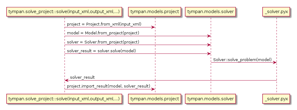
Python call graph